In the world of nesting, tube can be quite different to work with than plate. With plate, there is a level of nesting freedom that fabricators don’t get with tube. The nest tends to be more open, and shops have the ability to nest along the length and width of the sheet, whereas on the tube side, because they are working with only one direction and the part takes up the majority of space, there is a lot less room for error. Shops have to be a lot better at optimization with tube nesting because the smallest difference in part order or orientation can really tank the utilization.
Common Misconceptions
From a more general nesting perspective, it is not uncommon for fabricators who are working with nesting software to want to attempt to perform manual nesting. In some cases, these fabricators think they can do what the software is designed to do on their own. While some have the insight to create a tight nest, it may take them hours to come up with results that the nesting software could determine in minutes.
Nearly always, the software offers as good or better results in a fraction of the time. However, it can be hard to break that manual mentality. With a younger generation moving into the fabrication space, it is less common to see this reliance on manual nesting, both on the plate and tube side. And after side-by-side trials, nesting software proves how efficient and versatile it is.
When it comes to tube processing, many shops do not realize how varied material quality can be. When they are working with manual machines like saws, variability in material is less problematic. But when these shops move away from manual to more CNC cutting machines, this variability can cause problems.
A CNC machine can pick up on even the smallest changes in the material. If the machine doesn’t have something like touch probing to adjust for that slight material difference, fabricators may find themselves getting parts that look a bit different from what they’d expect, especially compared to manually cut parts. It’s important to account for material variability wherever possible.
Rectangular tube presents an additional challenge related to material variability. It is not uncommon for the radius to vary on a rectangular tube. When a program that is based on a specific size or radius of stock is generated, the cut quality can suffer if the CAD model is not changed to accurately reflect the actual material being cut.
Nesting for Machine Capabilities
One of the first things a shop needs to consider when it comes to tube processing optimization is nesting based on the type of cutting machine it is working with.
Nesting can work for everything from a simple sawing machine that just makes end cuts all the way up to complex laser machines with advanced part handling and loading/unloading capabilities. However, the nesting capabilities will directly relate to the type of machine being used.
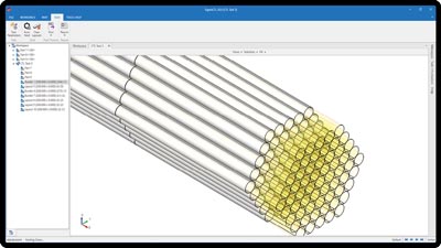
On sawing machines, the nesting software will need to know specific parameters, such as if it will be cutting in bundles. The software will optimize the nest to make sure that the saw can cut the largest number of sticks possible at the same time.
With a standard laser machine, it is important to understand that some of the chucking systems can leave a significant dead zone on the stick. For example, if the chucks are holding a 10- to 20-in. length at the end of the stick, the torch won’t be able to access this area and therefore will not be able to cut it.
In these cases, something like a dead zone nesting feature can help maximize material usage. With this, fabricators supply the software with all parts and the software analyzes them to see if any are simple or long enough to be placed in this dead zone so that the end of the stick can be used. So long as there are no cutting features, it most likely will be placed in this dead zone.
On more advanced machines with complex part loading and material handling systems, chucking systems also come into play. For example, some tube cutting machines have four large chucks that are able to perform all material and stock handling. This type of machine and chucking system is able to switch from left-right cutting to right- left cutting by switching the chucks. The nesting algorithm in the software needs to know about these processes to take advantage of this machine feature. Fabricators can simply tell the nesting engine what machine it is working on and it will look at all the features and capabilities available to take full advantage of them and nest accordingly.
Nesting for Material Optimization
Support for common-line cutting is a great way to optimize material usage. However, it’s important to note that when 1D nesting for tube machines is performed, using a common-line cut rather than a kerf distance can be the difference between fitting one more part on the end of the stick.
For non-bevel cutting machines, features like 4-axis compensation can be a big help for proper fits in the assembly process. Trimming extra material off in mitre or cope geometries using this feature will ensure a good, clean fit on the inside of the tube with whatever component it is being welded to in subsequent stages.
In these cases, the nesting engine can look at the toolpath rather than the actual 3D part geometry to determine how close the parts can be nested. Since the toolpath dictates what the finished part will look like, the software can nest a little bit tighter with this feature.
Nesting can work for everything from a simple sawing machine that just makes end cuts all the way up to complex laser machines with advanced part handling and loading/unloading capabilities.
Nesting for Optimized Program Run
For tube processing with laser machines, typically fabricators work with bundles of the same stick length. Most are buying from a vendor that supplies in very specific dimensions; 240 in. is a common one.
If a fabricator is working with the same stick length, the nesting software can be told to optimize for creating exact nests instead of optimize for material. The engine will then take a look at the parts and figure out the best utilization for one stick and repeat that program over and over again.
For fabricators working with different stick lengths, it’s important to ensure that the software allows for optimization of the best combination. If the engine has two different lengths input into it, it will be able to determine the best combination of sticks for optimal material utilization from shop floor stock.
Nesting also can allow fabricators to specify which length they want to use. For example, a shop can specify that the software use up all the shortest lengths first to go through as many remnants as possible before moving on to actual stick inventory.
Creating nests that optimize for program runs rather than material makes sense for shops producing very large batch runs, where there are thousands of parts to cut. It may be more financially beneficial for them to reduce the time an operator spends taking off and sorting different parts because the nesting programs differ so much from stick to stick.
Since they are not doing much unloading or other operations, low-volume/high-mix shops can turn up all the optimization settings to ensure that material utilization is maximized. It really makes more sense to prioritize material over program optimization in these applications.
It’s important that fabricators look at the controls and see what works best for the shop’s needs. For example, if a shop is working with large batch runs, the machine may include more advanced features like loading and unloading. In this case, it won’t matter if all programs are different because the machine is able to process quickly and take the place of the operator, freeing him up for other tasks. Good nesting software gives shops the ability to adjust the dials and optimizations as they see fit.
Nesting can work for everything from a simple sawing machine that just makes end cuts all the way up to complex laser machines with advanced part handling and loading/unloading capabilities.
Calculating Time and Cost
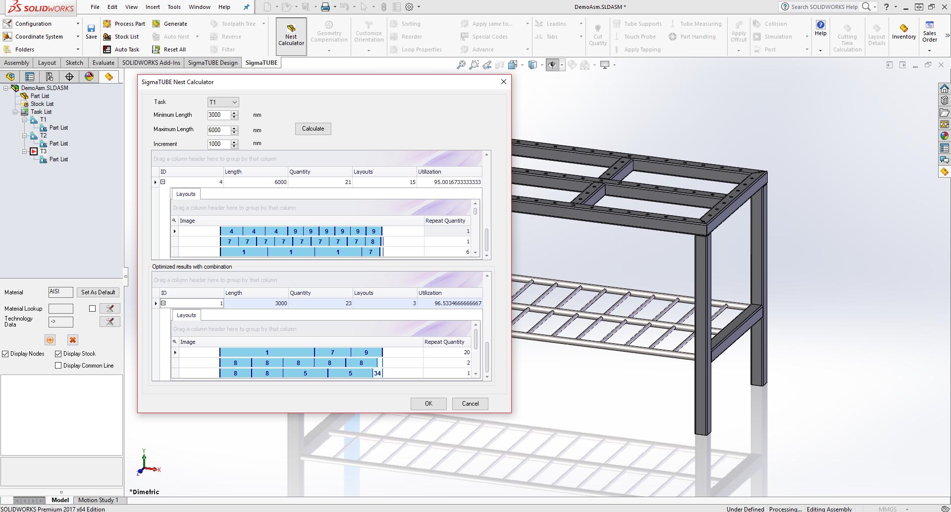
A calculator is another good tool to have when it comes to tube processing. One of the main advantages is that the calculator allows shops to input metrics and determine time and costs without having to generate the program for the machine.
Fabricators can just type in all the different stick lengths available on the shop floor and can even specify which length to start with and work up to. The nesting software calculator looks at all aspects and determines the best resulting process based on the stick lengths available or even the best stick lengths for a given batch.
This is a great feature for bidding on jobs. It gives shops the flexibility to see if a job is worth it and combine available stick lengths for optimized material usage.
Published in Canadian Fabrication & Welding, February 2022
“Tackling Tube Nesting” by Lindsay Luminoso, Associate Editor
https://www.canadianmetalworking-digital.com/february-2022/Tackling-Tube-Nesting
Interview with Dakota Baird, Product owner for tube/bar and import for SigmaNEST