The complex geometry and nesting challenges for beveled parts has historically been a long process of trial and error. Despite wasted time and a high scrap rate, the part is still likely to require extensive manual clean-up. Bevels are edge cuts typically used to prepare steel plate parts for welding. Professional fabricators have long relied on CNC machines and nesting software to fine tune and automate the beveling process.
Beveling can include a variety of applications – each with a unique set of challenges. Additionally, thermal cutting, abrasive cutting, and machining all have a completely different set of considerations when performing bevel cuts on plate, tube, wood, composites, and so on. Regardless of how simple or complex the part is, the process requires experience and a thorough understanding of machine and material.
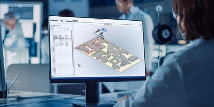
From design to production, SigmaNEST makes the beveling process intuitive. As your parts are nested, beveled edges are taken into consideration automatically and nests are optimized around the cutting tolerances required to produce accurate edge bevels. In addition to automatic bevel transitions, SigmaNEST gives visual updates to allow operators to double-check quality in real time.
As the industry leader in bevel processing, SigmaNEST delivers accurate bevels with precision and speed. SigmaTEK’s Director of Product Management, Paul Ikeda, discusses three best practices fabricators should consider when designing bevels.
Best Practices for Designing for Bevel:
1. Know the Machine
The first step in designing parts for beveling is to have a good grasp of the feasibility of the project. There are many pitfalls that can be avoided during and after programing. A common oversight before programming begins, is assuming your bevel machine can cut every bevel that can be designed. Just because something is modeled in 3D doesn’t necessarily mean it can be accomplished with the fabrication equipment in the shop. The draftsman can model almost any shape, but it doesn’t guarantee that the programmer or operator can cut it. Paul recommends avoiding these three messy situations:
i. Complex bevel corners
Design engineers should consider:
1) whether the machine is able to reach all the surfaces of the bevel cut,
2) the part not be freed from the sheet prematurely; and
3) if the machine has to spend too much time in the same area, there will be heat distortion issues.
ii. Variable bevels
Does your machine support changing its tilt and rotor while cutting? If not, certain bevels could greatly reduce cutting speed and create bottlenecks in production.
iii. Max tilt angle
What is the maximum combined angle for a bevel or corner with bevels? Beyond the maximum angle, the machine may error or require a mechanical reset maneuver to continue, resulting in delays and scrapped parts. A 3D simulation of the cutting process, such as that offered by SigmaNEST, allows engineers to digitally evaluate bevel feasibility during the design process.
2. Maximize Resource Usage
SigmaNEST improves efficiency in five key areas, known as the 5 M’s™ of optimization: material, motion, manpower, management and machines. Improving performance in these five areas allows fabricators to maximize production throughput and profitability. Paul offers insight into how design for manufacturing can affect each one:
i. Material utilization
“Transitioning from one bevel to another by using corner loop transitions requires additional nesting clearance which results in more scrap. Consider the size and shape of these loops during programming or utilize swarfing (cutting and tilting while moving) if your machine supports it,” recommends Paul. You can also select a nesting software that offers a no corner-loops option when generating NC code.
ii. Motion optimization
According to Paul, swarfing may improve cycle time, cut down on pierces and increase material utilization, but may reduce edge quality and add testing time. “Depending on the part, it may not be the best bevel cutting technique to use in all cases,” he explains.
iii. Manpower efficiency
The designer and programmer may decide not to include a full bevel (or possibly any bevels) in the cutting process, planning instead to hand- cut or grind the required chamfers as another shop floor operation step. However, taking advantage of the programming software to replace manual labor with machine-cut bevels can save time and affect consistency of quality.
iv. Management of data
Most major CAD systems support a concept that allows different configurations or multiple versions of the same part. In the early stages of the design process, it is important to consider the manufacturing steps needed to produce a part. A part file may have a bevel and non-bevel version. Rather than memorize your part library, you can use CAD tools like configurations or revisions to help streamline your production workflow and overall data storage.
v. Manufacturing automation
Paul recommends designing parts so that there is little room for error and the need for human intervention is limited. If the part is well-designed, the programmer or programming software can quickly and/or automatically generate a toolpath to drive the cutting machinery and produce ready-to-ship parts. While it may not always be possible to cut a part with just one machine, take time to consider how to streamline your current process. It may be useful for the designer and plant manager to walk through the steps of a job from start to finish.
3. Flexibility
Flexibility in the production process is very important. Your programmer should have the confidence and ability to make changes on the fly. Being able to add, edit or remove bevel features to prepare the part for each step in the manufacturing process has become a respected and vital skill. Make sure your process production team is properly aligned to make these changes so a small hiccup doesn’t turn into hours of downtime.
Although part modelling or programming approaches may vary, the most important thing to consider is the customer’s intent. If you are a fabricator producing your own parts, the intent should be well-understood. It may be a heavy structural part that requires some weld preparation. Alternatively, the part could be aesthetic in nature or a critical exterior component that must meet high tolerance requirements. In either case, it’s important to ensure that the design works all the way down to the finished part, meeting the goal of the piece. Successful teams keep intent in mind and see reduced resource waste and increased profitability.
Feasibility, resource management and flexibility all play an important role in designing beveled parts. By adopting these design considerations, viewing your machine processes holistically and knowing the process backwards and forwards, design decisions can be made in ways that are feasible and flexible to reduce cost and improve efficiency in the long run.
Learn how SigmaNEST can work with your bevel machine by visiting our Bevel Cutting page or contact us today to learn more.